Blog Catch Up: This really happened in April 2019, although the wording of the text makes it seem as if it happened today.
Next up were the wheels. I wanted the rims to be partly rusty so I made them a multi-step affair:
- Primer, from a rattle can
- Sprayed them with a Tamiya red brown color, from a rattle can
- A very light coat of hair spray
- Airbrushed the final color (Vallejo Silver grey)
When the final coat had cured I used a wet cotton swab to gently and
partly remove the top coat, revealing the red brown color below.
Here is the result, with tires attached:

Late date addition:
I did not take any more pictures from the actual build. But I thought I would share some experiences I had during the build. I will be referring to the Heller build instructions.
Three-point linkage
The first thing concerns the short arms that act as the attaching points between the hydraulic system and the three-point linkage. Those arms are part C16 attached to the power line very early in the build (step 2), and are shown encircled in the photo below.
These short arms are supposed to be able to swing freely up and down, and C16 shall not be glued down, but be held in place by part B13. The arms on my model did also swing freely, originally. But while my applied turpentine wash was drying I forgot to make sure that the arms did not get stuck. But of course they did, so when I reached the last step in the build (step 59), and was about to attach the three-point linkage, the linkage lifting arms did not reach those short arms. I had to use some considerable force, applied with a pair of pliers, to make the arms “swing” down. Fortunately nothing broke.
Lesson learned: Make sure these arms do not get stuck!
Rear wheel axles
Another mistake I made concerned the rear wheel axles. At some point during the build I realized that one of the axles was rotated a half turn. A rectangular hole that would eventually accept and hold the righthand mudguards was facing down instead of up.

The mistake was made in steps 20 and 21 (see below). The wheels are designed to be able to turn, and in step 20 axle parts D5 and D2 are glued together, but part D24 (part of the fixed axle housing and not part of the wheel rim) shall not be glued to the axle parts. However, the connection between parts D5 and D2 did not seem very sturdy, and I did not want the large rear wheels to wobble around so I decided to skip the “turning wheel” option and glue all parts in steps 20 and 21 together. The potential problem with this is in step 21. Here you must be aware of the fact that part B22 will later (in step 23) be attached to a hole in part D24, which in turn must decide the orientation of parts D14 and D15 in step 21. This to make sure the hole in D24 for part B22 faces forward while at the same time the rectangular hole in D14+D15 faces up (to accept the mudguard). And this must be true for the axle assemblies on both sides (left and right). Here somewhere I f-d up. Not a very big deal in the end, but embarrassing all the same. I managed to attach the mudguard anyway, and the misplaced hole on the underside of one of the axles does not show.


Linkage and pedals
This is not about a mistake on my part but about the kit itself. In step 30 you assemble some kind of pedals and linkage, and then, in step 31, you attach those assemblies to the tractor.
The first problem is that, in my opinion, part B16 is a little too short! It barely reaches part B22 (shown earlier in step 23). It is supposed actually fit in a hole in B22, but does not reach that far and I had glue it to B22 outside of the hole. You might want to find a way to lengthen B16.
The second problem here was a pedal that shall be inserted in another hole in B22, just outside of the previously mentioned hole. The pedals (one for the left side and one for the right side) are assembled in steps 46 and 47, and attached to the tractor in step 48 (shown as subassembly 46).
The problem is the receiving hole in B22. It is very shallow, allowing for a very weak joint only. I would recommend that you try to make the hole deeper using a drill bit. But then you must remember do that before you attach B22, which is way back in step 23! I did not realize this problem until it was too late, and had no way of reaching B22 with a drill bit and pin vise.
Front wheel linkage
The next thing I want to point out is an error in the build instructions. It concerns steps 34 and 36, where the front wheel linkage is assembled. Arrows in the instructions are intended to show where the parts shall join. Unfortunately the arrows point at the wrong locations. Should be as indicated in blue, and not as the original black arrows show.
Hood
When you look at steps 53 and 54 in the build instructions you get the impression that you shall first assemble the hood and then snap it onto the hinges below the radiator. It also looks as if it shall be possible to open and close the hood.
This is however not true! Unless my radiator is installed wrongly, but I cannot see how that would be. If you snap the assembled hood onto the hinges it will not be possible to lower it since it will snag on the upper part of the radiator. Fortunately I detected this before the hood had completely cured and was able to pry it apart and re-assemble it “in situ”.
Exhausts
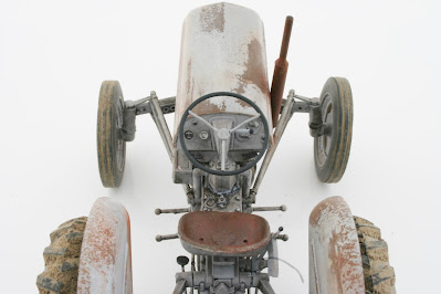
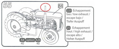
This is just a tip. You have an option to choose between a low and a high exhaust. The low exhaust has a hole at the end, making it look like the end of an actual pipe. The high exhaust lacks this hole, making the end look more like a rod than a pipe. If you choose the high exhaust you might want to drill a hole in the end before you install it.
I did not, since I did not think about this until the exhaust was already in place, but painted the end jet black instead. Good enough!
After reading all this you might think that I am not satisfied with the kit, and I must admit that the kit itself, and its instructions, had some weak points. But I still believe that the model will come out OK in the end. Of course I will post some pictures once I feel that I'm done.


